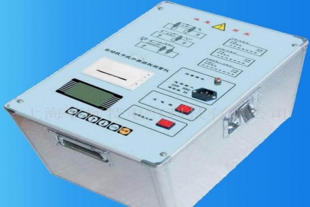
The Cable Fault Tester is used in power operation and maintenance for quickly locating power cable faults.
(especially high-voltage XLPE cables) at the fault point. It is typically not a single instrument but a combined system that includes two main stages: “fault distance measurement” and “precise pinpointing”.
The following is a detailed explanation of the core principles, classification, and workflow of this system:
1. Core Components and Functions
A complete cable fault testing system typically consists of three components:
Flashover Tester (Main Unit): Used for rough measurement, determining the fault nature and calculating the approximate distance to the fault point (accuracy typically at the meter level).
Path Tracer: Used to detect the buried path and depth of the cable (if the path is unknown).
Pinpointer (Acoustic-Magnetic Synchronous Detector): Used for precise pinpointing within the rough measurement range, finding the exact ground location of the fault point (accuracy can reach centimeter level).
(Optional) High-Voltage Signal Generator (Arc Burner/Impulse Discharge Device): For high-resistance faults, this device is needed to apply high voltage to break down the fault point, generating acoustic and electromagnetic waves for detection by the pinpointer.
2. Fault Type Classification
Before testing, the fault type must be determined first, as different fault types require different distance measurement methods:
Low-Resistance Fault: Insulation resistance below several hundred ohms (even close to 0Ω), such as metallic short circuits.
High-Resistance Fault: Very high insulation resistance (several megohms to several thousand megohms), but breaks down under high voltage. This is the most common fault in high-voltage cables (such as moisture ingress and aging).
Open Circuit Fault: Cable core wire is broken, with infinite resistance.
Flashover Fault: Normally good insulation, only instantaneously breaking down when the voltage rises to a specific value.
3. Main Distance Measurement Methods (Rough Measurement)
The Flashover Tester typically integrates the following methods, automatically or manually switching based on fault type:
A. Low Voltage Pulse Method (LVP)
Applicable to: Low-resistance faults, open circuit faults, and measuring full cable length.
Principle: A low-voltage pulse is transmitted into the cable; when it encounters an impedance mismatch point (break point or short circuit point), a reflected wave is generated. The time difference between the transmitted and reflected waves is measured
Features: Simple, safe, no high-voltage equipment needed, and waveform is intuitive.
B. Impulse Flashover Method
Applicable to: High-resistance faults and flashover faults (most commonly used).
Principle: In conjunction with a high-voltage signal generator, DC high voltage or impulse high voltage is applied to the cable to force the fault point to break down and discharge. The current traveling waves generated at the moment of discharge reflect multiple times between the test end and the fault point. The instrument captures these traveling wave signals to calculate the distance.
Features: Can solve high-resistance problems, but requires high-voltage equipment and careful attention to safety during operation.
C. Direct Flashover Method
Applicable to: Some flashover faults (high-resistance faults with extremely low leakage current).
Principle: DC high voltage is applied; when the voltage rises to the breakdown point of the fault, the voltage and current mutation waveform is recorded.
Current Status: Gradually being replaced by the impulse flashover method in modern instruments, as the impulse flashover method produces clearer waveforms.
D. Secondary Pulse Method / Multiple Pulse Method (Arc Reflection Method)
Applicable to: High-resistance faults (the most advanced technology currently).
Principle: At the moment the fault point breaks down and arcs, the instrument automatically transmits a low-voltage pulse. At this moment, the fault point appears in a “low-resistance” state under the arc effect, and the low-voltage pulse produces a clear reflected wave as if testing a low-resistance fault. The instrument superimposes and compares the “waveform during arcing” with the “waveform without arcing”, and the difference point is the fault point.
Advantages: The waveform is extremely simple and clear (similar to the low-voltage pulse method), greatly reducing the difficulty of interpreting high-resistance faults, and is a standard feature of current high-end testers.
4. Precise Pinpointing Methods (Finding the Exact Location)
After the Flashover Tester tells you “the fault point is 356 meters from the test end”, you need to use the pinpointer near this location (typically within a ±10 meter range) to find the exact ground location.
Acoustic-Magnetic Synchronization Method: The most mainstream method.
Principle: When high-voltage impulse discharge is applied, the fault point emits a “pop” sound (acoustic wave) and electromagnetic wave.
Operation: The pinpointer simultaneously receives acoustic and electromagnetic waves. The electromagnetic wave travels extremely fast (serving as a trigger reference), while the acoustic wave travels slowly (serving as a delayed signal). The instrument displays the time difference or synchronization indication between the two.
Judgment: When the probe is moved directly above the fault point, the sound is loudest and the acoustic-magnetic time difference is smallest (or the synchronization indication is most pronounced).
Step Voltage Method: Suitable for outer sheath damage ground faults, locating by measuring surface potential gradients.
5. Standard Testing Procedure
Safety Measures: Confirm the cable is de-energized, both ends are disconnected from equipment, fully discharged, and grounding wires are attached.
Diagnostic Analysis: Use a megohmmeter (megger) to measure insulation resistance, and use a multimeter to check continuity, determining the fault type (low-resistance/high-resistance/open circuit).
Path Detection (if needed): If the cable route is unknown, first use the path tracer to detect the path and burial depth.
Rough Distance Measurement:
If low-resistance/open circuit: Directly use the low-voltage pulse method.
If high-resistance: Connect the high-voltage generator and use the secondary pulse method or impulse flashover method for distance measurement.
Precise Pinpointing:
Carry the pinpointer and headphones to the vicinity of the rough measurement distance.
Activate the high-voltage generator for periodic impulse discharge.
Move the probe along the cable path, listen for the discharge sound, and find the point of maximum sound.
Excavation and Repair: After confirming the location, excavate and repair, then retest.
6. Common Brands and Selection Recommendations
International Brands: Baur (Austria), Megger (UK), SebaKMT (Germany). Features: high precision and powerful software, but expensive.
Domestic Brands: Wuhan Moen, Huatian Electric, Qingdao Hanhe, Baoding Ruixiang, etc. High cost-performance ratio, very mature technology, fully meeting national standard requirements.
Key Selection Criteria:
Whether it has secondary pulse/multiple pulse functionality (strongly recommended, significantly reduces the difficulty of high-resistance fault testing).
The energy capacity of the high-voltage generator (the greater the energy, the easier it is to break down high-resistance faults, the louder the sound, and the easier it is to pinpoint).
The anti-interference capability and sensitivity of the pinpointer.
7. Safety Warnings
High Voltage Danger: When testing high-resistance faults, a high-voltage generator must be used (typically up to 8kV-32kV). The test area must be fenced off, with dedicated personnel guarding. Touching high-voltage lines is strictly prohibited.
Residual Charge: After testing, a large amount of charge may remain on the cable. A dedicated discharge rod must be used for thorough discharge before making contact.
If you need specific wiring diagrams, waveform case analysis for a specific fault type, or detailed parameters of relevant national standards (such as DL/T 474.5), please let us know!