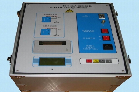

Loop Resistance Tester Commonly Known as Contact Resistance Tester or Micro-ohmmeter
It is a precision instrument specifically designed for measuring the DC resistance of conductive loops in high-voltage switchgear (such as circuit breakers and disconnecting switches), busbar connections, cable joints, and other components.
Its core function is to detect whether the contact of conductive loops is good. Excessive contact resistance typically indicates loose connections, oxidation, corrosion, or contact erosion, which can cause heating during operation and, in severe cases, lead to equipment burnout or explosion accidents.
The following are the core technical points of this instrument:
1. Core Testing Principle: DC Voltage Drop Method (Four-Wire System)
High Current Injection: The instrument internally outputs a constant high DC current (typically 100A, 200A; high-end models can reach 400A or 600A).
Why High Current? Small currents cannot break through the oxide film on contact surfaces, resulting in inflated and unstable resistance readings. Only high current approaching or exceeding the equipment rated current can truly simulate operating conditions, break through the oxide layer, and measure real contact resistance.
Four-Wire Measurement (Kelvin Method):
Two thick wires are used for current output (
R=U/I, the instrument automatically calculates and displays the resistance value.
2. Main Application Scenarios
High-Voltage Circuit Breakers: Measures the contact resistance of break points (main contacts) to determine whether contacts are burned or spring pressure is insufficient.
Disconnecting Switches: Detects the contact condition between knife edges and stationary contacts.
Busbars and Cable Joints: Checks whether bolted connections are tight and whether contact surfaces are oxidized.
Welding Quality Inspection: Such as welding quality of transformer winding connection points and copper-aluminum transition joints.
3. Key Performance Indicators
Output Current: Common specifications include 100A, 200A, 400A, 600A. Higher current provides stronger anti-interference capability and more realistic test results (especially for large-capacity circuit breakers).
Measurement Range: Typically at
±(0.5% reading + 2 digits) or higher.
Protection Functions: Includes back-EMF protection (prevents inductive discharge from damaging the instrument), overheat protection, over-current protection, etc.
4. Relevant Standards
The testing process and result judgment are mainly based on the following standards:
GB 50150-2016 "Standard for Hand-Over Test of Electric Equipment in Electric Equipment Installation Engineering"
DL/T 596-2021 "Preventive Test Code for Electric Power Equipment"
GB/T 11022 "Common Technical Requirements for High-Voltage Switchgear and Controlgear Standards"
Typical Criteria:
The measured value should comply with the product technical documentation requirements.
If not specified, generally the measured value should not exceed 1.2 times the factory value.
For three-phase equipment, the unbalance rate of three-phase resistance values should generally not exceed 20% (specific to equipment type).
5. Operating Precautions (Very Important)
Power Disconnection and Discharge: Testing must be performed after the equipment under test is completely de-energized and fully discharged (especially for capacitive loads or induced voltages from nearby live conductors). Testing under energized conditions is strictly prohibited!
Wiring Sequence:
First connect the current leads (thick wires), then connect the voltage leads (thin wires).
Voltage clamps should be placed inside the current clamps (closer to the center of the test object) to eliminate the influence of current lead contact resistance.
Ensure firm clamping, clean the contact surface by grinding, and remove the oxide layer.
Test Duration: Since it is a high-current inductive load (such as a circuit breaker coil), current stabilization takes time. Modern instruments typically have an "auto-timing" function that starts timing after current stabilizes (typically energization time is no less than several seconds to tens of seconds, depending on standard requirements).
Disconnection Sequence: After testing, the instrument automatically cuts off current and provides a prompt. Always wait for the instrument to display "Test Complete" or for current to return to zero before removing test leads. It is strictly prohibited to directly disconnect the test clamps while high current is flowing, as this will generate intense arcing, burn contacts, or damage the instrument.
6. Common Fault Analysis
Displaying "Overload" or current unable to rise: May be due to open circuit, poor contact (clamps not tight enough), or measured resistance far exceeding the range.
Large data fluctuations: High interference at the test site, poor grounding, or severe oxidation of the tested contact surface leading to unstable contact.
Higher values: Contact erosion, loose connecting bolts, reduced conductor cross-section, or test lead contact resistance not eliminated (wiring error).
If you need operation videos for specific models, resistance limit tables for different voltage level circuit breakers from national standards, or test report templates, please feel free to contact us!