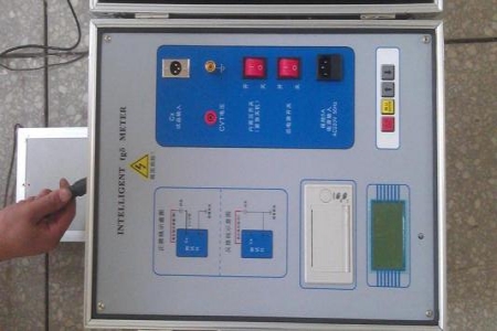


The ultrasonic partial discharge detector is a specialized instrument for detecting
If you would like an article about Ultrasonic Partial Discharge Detectors with specific details and technical information, the following is an article compiled from existing materials.
Ultrasonic Partial Discharge Detector Explained
Introduction
The ultrasonic partial discharge detector is a portable instrument specifically designed to detect partial discharge phenomena in power equipment. Partial discharge occurs in insulation systems when the applied voltage reaches a certain threshold, causing localized discharge. This phenomenon can degrade insulation performance and even cause equipment failure. The ultrasonic PD detector captures the ultrasonic signals generated by partial discharge to help assess the insulation condition of power equipment.
Working Principle
The working principle of the ultrasonic partial discharge detector is based on the ultrasonic signals generated during partial discharge. When partial discharge occurs inside power equipment, it produces ultrasonic signals with frequencies above 20kHz. These signals propagate to the external environment through gaps and holes on the equipment surface, where they are captured by the detector sensors. The detector converts these signals into electrical signals, which are then analyzed and displayed by the built-in signal processing unit. In this way, the detector helps staff locate PD sources and assess their severity.
Main Features
Portability: Lightweight design for easy on-site transport.
Multi-Sensor Support: Supports different types of sensors such as ultrasonic sensors to accommodate various detection needs.
High Sensitivity: Capable of detecting extremely weak discharge pulses.
Strong Anti-Interference Capability: Uses advanced anti-interference technology to operate normally in complex electromagnetic environments.
Multi-Function Display: Typically equipped with a large LCD screen that clearly displays test waveforms and data.
Data Recording and Analysis: Features data recording capability to save test results for subsequent analysis.
User-Friendly Interface: Simple and intuitive operation for field technicians.
Technical Parameters
Technical parameters of ultrasonic partial discharge detectors may include:
Frequency Response Range: Typically 20 kHz - 200 kHz.
Sensitivity: Typically between several picocoulombs (pC) to tens of picocoulombs.
Display: Large LCD screen.
Battery Life: Typically capable of continuous operation for several hours.
Weight: Lightweight and portable.
Anti-Interference Capability: Can operate normally under a certain level of electromagnetic interference.
Usage Method
Startup Preparation: Power on the ultrasonic partial discharge detector.
Calibration: Calibrate the instrument correctly according to the device manual.
Connecting Sensors: Correctly connect the ultrasonic sensor to the detector.
Start Testing: Place the sensor at the test position and begin data collection.
Data Analysis: Observe the discharge pulse waveform on the detector screen and record data.
Data Storage: Save important test results.
Application Scenarios
Power Equipment Maintenance: Used for routine inspection and maintenance of high-voltage equipment such as power transformers, cables, and generators.
Fault Diagnosis: When equipment abnormalities occur, diagnose fault causes through partial discharge detection.
Product Quality Control: Quality control of power equipment during production to ensure the insulation performance of factory equipment meets standards.
R&D: Used to evaluate the effectiveness of new insulation materials or structures during the development of new power equipment.
Case Study
Case 1: A power company used an Ultrasonic PD Detector during routine inspection to test high-voltage switchgear in a substation. During testing, slight partial discharge inside the switchgear was discovered. Through further data analysis, the PD location was identified, and corresponding maintenance measures were taken, preventing potential equipment failure.
Case 2: An electrical equipment manufacturer used an Ultrasonic PD Detector to test newly produced transformers before shipment. Through testing, one transformer was found to have insulation performance issues and was promptly repaired, ensuring product quality.
Conclusion
Ultrasonic PD Detectors play an important role in the power industry due to their reliable detection capability and flexibility. By using such testers, power enterprises can not only effectively prevent equipment failures but also significantly improve the overall reliability and safety of power systems. As technology advances, future detectors will become more intelligent and portable, further enhancing the efficiency and accuracy of partial discharge detection.
The above is an overview of Ultrasonic Partial Discharge Detectors. We hope this article provides relevant information and technical details about Ultrasonic PD Detectors. If you need more detailed information or specific case analyses, please feel free to let us know.