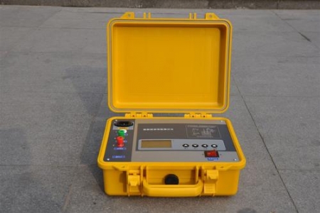


Working Principle of Partial Discharge Tester
Partial Discharge Testers detect by capturing electromagnetic waves, acoustic waves, or other physical phenomena generated during the partial discharge process. Common detection methods include:
Pulse Current Method: Couples the current pulses generated by partial discharge into detection impedance through coupling capacitors, then converts them into voltage signals for measurement.
Ultrasonic Detection: Uses ultrasonic sensors to receive acoustic wave signals generated during the partial discharge process.
Transient Earth Voltage (TEV) Detection: Detects transient voltages generated by partial discharge through sensors placed on metal enclosures.
Ultra High Frequency (UHF) Detection: Captures electromagnetic wave signals generated by partial discharge using UHF sensors installed inside or outside transformers.
Importance of Partial Discharge Testing
Early Warning: Partial discharge testing can promptly detect micro-defects in insulating materials, helping prevent potential serious failures.
Maintenance Planning: Data collected through regular testing enables more reasonable maintenance planning, reducing unplanned downtime.
Cost-Effective: Compared to repair costs after an accident, partial discharge testing is relatively low cost and offers high economic benefits.
Testing Steps
Preparation: Ensure the testing equipment is properly grounded and all necessary sensors and test lines are connected.
Calibration: Before formal testing, calibrate the test system using a calibration pulse generator to ensure measurement accuracy.
Adjust Gain: Adjust the amplifier gain according to actual conditions so that the injected pulse height is moderate, typically about 2 cm of the oscilloscope screen height.
Start Testing: Gradually increase the test voltage until partial discharge phenomena are observed. This voltage is the partial discharge inception voltage.
Data Analysis: Record the characteristic parameters of partial discharge, including the number and amplitude of discharge pulses, and conduct comprehensive analysis.
Practical Operating Guide
Instrument Preparation: Confirm all testing equipment is in good condition and ensure instruments are grounded.
Test Connection: Correctly connect test lines according to the manufacturer's instructions.
Calibration: Calibrate using a calibration pulse generator to ensure accurate measurement.
Adjust Gain: Adjust gain based on calibration results to make the signal appropriate.
Test Operation: Gradually implement according to test steps, paying attention to observe partial discharge phenomena.
Record Data: Record all key data, including the inception voltage and extinction voltage of partial discharge.
Analyze Results: Analyze based on recorded data to determine whether partial discharge phenomena exist.
Conclusion
Transformer Partial Discharge Testers are indispensable tools in power equipment maintenance. They help engineers promptly detect and address potential insulation issues, thereby ensuring the safe and stable operation of power systems. With technological advancement, future testers will become more intelligent and portable, further improving testing efficiency and accuracy.