
Darui Electric recommends:
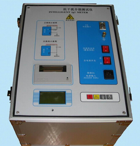
UsageDielectric Loss TesterWhen using, the supplied special high-voltage cable, although factory-tested and qualified, should still be kept away from the human body and low-voltage test leads during measurement。The instrument has a built-in voltage boosting device; attention should be paid to the insulation of high-voltage leads and personnel safety. In recent years, with the application research of oscillatory wave testing technology, dielectric loss measurement technology based on attenuation time constant measurement has gradually evolved. The Dielectric Loss Tester mainly utilizes the principle that capacitive reactance equals inductive reactance under resonance conditions. Based on classical dielectric loss theory and experimental results, three main sources of dielectric loss in XLPE cables have been identified: conduction loss, polarization/relaxation loss, and resistance loss of the semiconductive layer, which successively play dominant roles in the low, medium, and high frequency ranges.
The technology of dielectric loss testers has developed rapidly. The QS1 Schering bridge previously widely used in power systems is being replaced by intelligent dielectric loss testers. The new generation of dielectric loss testers all have built-in voltage boosting equipment and standard capacitors, featuring simple operation, accurate data, and convenient reading of test results. The dielectric loss tangent is also known as the dielectric loss factor or simply dielectric loss. Measuring the dielectric loss factor is a highly sensitive test item that can detect overall moisture ingress in power equipment insulation, deterioration, and both through and non-through local defects in small-volume test objects.
Functional Features of Dielectric Loss Tester
1. For instrument fault analysis.
2. Strong anti-interference capability, maintaining stable and reliable results even at substations with voltage levels of 500KV (or even higher). Not only capable of single-frequency testing, but also supports 45/55Hz dual-frequency testing.
3. Gradual voltage ramp up/down prevents capacitive rise effect, protecting test object and instrument.
4. Overcurrent/overload protection instantly cuts test power for safety.
5. Test cables made of silicone rubber and special insulation, flexible, ground-drag usable at 10KV.
Note: The above information and technical parameters are compiled and published by Yangzhou Darui Electric Co., Ltd.
Note: The above information and technical parameters are compiled and published by Yangzhou Darui Electric Co., Ltd.