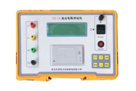


Transformer DC Resistance Tester: Principle, Usage and Application Introduction
The transformer DC resistance tester is a precision instrument specifically designed for measuring the DC resistance of transformer windings. This test is very important for detecting the material, welding quality, and connection integrity of transformer coils, helping to identify potential manufacturing defects and operational hazards.
Working Principle
The working principle of the transformer DC resistance tester is based on Ohm's Law. By applying a certain DC current to the winding and measuring the impedance, the resistance value of the coil is calculated. The specific steps are as follows:
DC Power Supply: The tester is equipped with an internal constant current source capable of generating DC current.
Measurement Circuit: DC current flows through the I+ and I- terminals to the coil under test, generating corresponding voltage values.
Voltage Detection: The V+ and V- terminals detect the voltage across the coil under test.
Data Processing: Through the built-in A/D converter and processor, the resistance value is automatically calculated and displayed on the screen.
Main Features
The main features of the transformer DC resistance tester include:
High Output Current: Capable of providing sufficient current to ensure measurement accuracy.
Wide Measurement Range: Can cover different ranges from low resistance to high resistance values.
Compact and Lightweight: Easy to carry and suitable for field use.
Simple Operation: Features automatic data processing and display functions, simplifying the operating procedure.
Safety Design: Equipped with automatic discharge and discharge indication functions to ensure safety.
Usage Method
Preparation:
Estimate the resistance value of the coil under test.
Short-circuit and ground the non-tested coils.
Connect the Tester:
Connect the I+, V+, V-, and I- terminals of the tester to the test specimen according to the correct wiring method.
Testing Process:
Turn on the power switch and wait for the instrument to be ready.
Select the appropriate resistance range based on the magnitude of the measured value.
Press the corresponding range switch and read the stably displayed resistance value.
If testing a large inductance specimen, allow the instrument to complete the discharge process after the test.
Precautions
Before testing, confirm that the equipment under test has been de-energized and fully discharged.
Ensure correct wiring to avoid measurement errors caused by incorrect connections.
When testing large inductance specimens, do not immediately disconnect the wiring after turning off the power to prevent injury from electromagnetic induction.
Application Areas
The transformer DC resistance tester is widely used in multiple areas of power systems, including but not limited to:
Transformer Manufacturing: Used for quality control during the production process.
Commissioning Tests: Acceptance testing of newly installed transformers.
Preventive Testing: Regularly inspect the condition of transformers to prevent fault occurrence.
Repair and Maintenance: Used for performance evaluation of transformers after repair.
Conclusion
The transformer DC resistance tester, with its high efficiency, precision, and multi-function features, plays an important role in transformer testing in power systems. By correctly using this instrument, the safety and reliability of power equipment can be effectively improved.
If you need more detailed information or content on other aspects, please feel free to let us know.