Many domestic substations have experienced expanded accidents due to lightning strikes, most of which are related to non-compliant ground grid resistance. The grounding grid serves both working grounding and protective grounding functions. When the grounding resistance is too large: during a ground fault, the neutral point voltage offset increases, potentially causing the healthy phase and neutral point voltage to be too high, exceeding insulation requirements and causing equipment damage. During lightning strikes or lightning surge attacks, due to the high current, very high residual voltage is generated, subjecting nearby equipment to back-flashover threats and reducing the lightning withstand level of the grounding grid's own protected equipment (overhead transmission lines and substation electrical equipment) live conductors, failing to meet design requirements and damaging equipment. At the same time, whether the grounding resistance of the grounding system is compliant directly affects the personal safety of substation operators and maintenance personnel. However, due to the corrosive effect of soil on grounding devices, as operating time increases, the grounding devices become corroded, affecting the safe operation of the substation. Therefore, regular monitoring of ground grid resistance must be strongly emphasized. For in-service substation ground grid resistance measurement, interference from system current flowing into the ground grid and interference between test lead wires can cause significant errors in test results. Especially for large grounding grids with very low grounding resistance (generally below 0.5Ω), even subtle interference can have a significant impact on test results. If the ground grid resistance test is inaccurate, it not only damages equipment but also causes unnecessary losses such as erroneous ground grid modifications. Based on my research on ground grid impedance testing methods, the following is a summary:
II. Grounding Resistance Testing Principles and Methods
When testing the grounding impedance of a grounding device, the current electrode should be placed as far away as possible. Typically, the distance dcG between the current electrode and the edge of the grounding device under test should be 4 to 5 times the maximum diagonal length D of the device under test (parallel wiring method), and in areas with uniform soil resistivity it can be 2 times or more (triangular wiring method). The voltage lead length is 0.618 times the current lead length (parallel wiring method) or equal to the current lead length (triangular wiring method).
1. Potential Drop Method
The potential drop method for testing the grounding impedance of a grounding device arranges the test circuit according to Figure 1 and meets the requirements for test circuit arrangement.
G—Grounding device under test; C—Current electrode; P—Potential electrode; D—Maximum diagonal length of the grounding device under test; dCG—Distance between the current electrode and the edge of the grounding device under test; x—Distance between the potential electrode and the edge of the grounding device under test; d—Test distance interval;
The current I flowing through the grounding device G under test and the current electrode C causes changes in ground potential. The potential electrode P moves outward from the edge of G along a direction at 30°~45° to the current circuit, testing the potential difference U between P and G at intervals of d (50m, 100m, or 200m), and plotting the curve of U versus x. The flat portion of the curve is the potential zero point, and the potential between it and the curve point is the potential rise U of the grounding device under test at the test current. The grounding impedance of the grounding device is:
Z=Um/I
If it is indeed difficult to lay the potential test line at an angle to the current line, it can be laid along the same path, but the maximum possible distance should be maintained.
If the flat point of the potential curve is difficult to determine, it may be due to the influence of the grounding device under test or the current electrode C, in which case consider extending the current circuit; or the underground conditions may be complex, in which case consider using other methods to test and verify.
2. Current-Voltmeter Three-Pole Method
a) Linear Method
Laying the current line and potential line in the same direction (same path) is called the linear method in the three-pole method, see Figure 2; dcG meets the test circuit arrangement requirements, dPG is typically (0.5~0.6) dcG. The potential electrode P should be moved three times along the line direction between the grounding device G under test and the current electrode C, each move distance being about 5% of dcG. The test is acceptable when the error of three test results is within 5%.
Large grounding devices are generally not suitable for linear method testing. If conditions restrict and it must be used, care should be taken to keep the current and potential lines as far apart as possible to reduce the effect of mutual inductive coupling on test results.
G—Grounding device under test; C—Current electrode; P—Potential electrode; D—Maximum diagonal length of the grounding device under test
dCG—Distance between the current electrode and the edge of the grounding device under test; dPG—Distance between the potential electrode and the edge of the grounding device under test;
b) Angular Method
Where conditions permit, the testing of large grounding device impedance adopts the current-potential line angular arrangement method. dcG meets the test circuit arrangement requirements, generally 4D~5D; for ultra-large grounding devices, it should be as far as possible. The length of dPG should be similar to dcG. The grounding impedance can be corrected using formula (2).
(2) where
θ---Angle between the current line and potential line;
Z''--- Test value of grounding impedance.
If the soil resistivity is uniform, isosceles triangle wiring with equal dcG and dpG can be used, with θ approximately 30°, dcG=dpG=2D, applying grounding correction formula 2.
3. Grounding Resistance Tester Method.
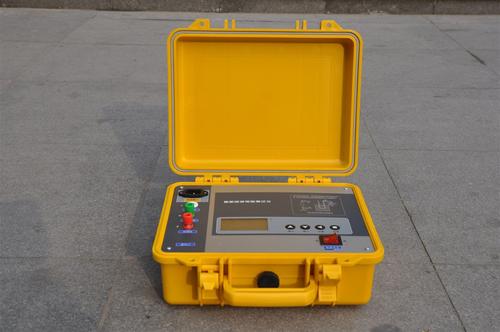
Figure 3 shows the wiring method for testing ground grid resistance using a grounding resistance tester; the testing principle, wiring, and requirements are similar to the three-pole method.
1. When using the three-pole method for measurement, the E pole must be shorted to P1. However, when the ground grid resistance is very low (≤0.5Ω), to improve measurement accuracy and reduce the influence of instrument-to-ground-grid lead resistance and contact resistance on measurement results, the E-P shorting plate can be opened. To reduce the error caused by contact resistance, a separate lead wire must be connected to the ground grid test point.
Note:
1. E--Connect to the ground grid under test;
2. P1--Connect to the ground grid under test;
3. P2--Connect to the measurement voltage line (its length is 0.618 times the current line length);
4. C--Connect to the measurement current line (its length is 4 to 5 times the diagonal length of the ground grid);
III. Testing Precautions and Significance
The characteristic parameters of grounding devices are mostly closely related to the moisture level of the soil. Therefore, the condition assessment and acceptance testing of grounding devices should be conducted as much as possible during dry seasons and when the soil is not frozen, and should not be performed during or immediately after thunder, rain, or snow. Through actual measurement, reliable data is provided for our rectification work. For the grounding condition of substation ground grids, rectification and optimization plans are proposed to bring the grounding resistance of the ground grid into compliance, thereby effectively preventing personal injury caused by step voltage from equipment insulation damage or further equipment damage. This ensures the safe operation of electrical equipment and creates a safe and reliable working environment for substation personnel.