
☎
Service Hotline18952707000
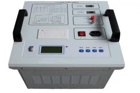
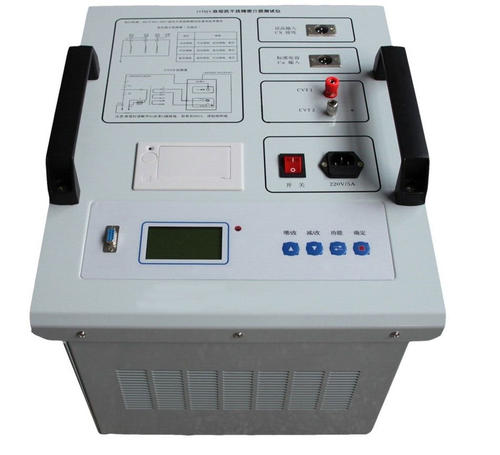
Dielectric loss tester is a high-precision testing instrument used in power plants, substations, and other field or laboratory settings to measure the dielectric loss tangent and capacitance of various high-voltage power equipment. The instrument is an integrated structure, built-in dielectric loss test bridge, variable frequency voltage regulating power supply, step-up transformer and SF6 high stability standard capacitor. The test high-voltage source is generated by the internal inverter of the instrument, and is boosted by the transformer for testing the test object. The frequency can be changed to 45Hz or 55Hz, 55Hz or 65Hz, using digital notch technology to avoid the interference of power frequency electric field on the test, fundamentally solving the problem of accurate measurement under strong electric field interference. It is also suitable for occasions where power is supplied by generator after complete power outage. The instrument can be equipped with an insulating oil cup to test the dielectric loss of insulating oil.
Working Principle
Under the action of AC voltage, the dielectric consumes part of the electrical energy, which is converted into heat energy and causes loss. This energy loss is called dielectric loss. When an AC voltage is applied to the dielectric, there is a phase angle difference Ψ between the voltage and current in the dielectric. The complementary angle δ of Ψ is called the dielectric loss angle, and the tangent tgδ of δ is called the dielectric loss tangent. The tgδ value is a parameter used to measure dielectric loss. The instrument measurement circuit includes a standard circuit (Cn) and a test circuit (Cx). The standard circuit consists of a built-in high stability standard capacitor and a measurement circuit, and the test circuit consists of the test object and a measurement circuit. The measurement circuit consists of a sampling resistor, a preamplifier, and an A/D converter. The measurement circuit measures the amplitude and phase of the standard circuit current and the test circuit current respectively, and then uses a microcontroller to perform digital real-time acquisition and vector calculation to obtain the capacitance value and dielectric loss tangent of the test object. This instrument has built-in anti-interference measures to ensure accurate measurement under external electric field interference.
Technical Parameters
1
Operating Conditions
-5℃∽40℃
RH<80%
2
Anti-interference Principle
Frequency conversion method
3
Power Supply
AC 220V±10%
Frequency unlimited
4
High Voltage Output
0.5KV∽10KV
Every 0.1kV
Accuracy
2%
Maximum Current
200mA
Capacity
1500VA
5
Self-excitation Power Supply
AC 0V∽50V/15A
45HZ/55HZ
6
Resolution
tgδ: 0.001%
Cx: 0.1pF
7
Accuracy
△tgδ:±(reading*1.0%+0.040%)
△C x :±(reading*1.0%+1.0PF)
8
Measurement Range
tgδ
Unlimited
C x
15pF < Cx < 200nF
10KV
Cx < 60 nF
5KV
Cx < 100 nF
1KV
Cx < 200 nF
CVT Test
Cx < 200 nF
9
CVT Ratio Range
10∽10000
CVT Ratio Accuracy
0.1%
CVT Ratio Resolution
0.1
10
Dimensions
430(L)×330(W)×330(H)
11
Memory Size
80 groups, supports U disk data storage
12
Weight
28 Kg
Note: The above information and technical parameters are compiled and released by Yangzhou Dara Electric Co., Ltd.