Cable Fault Flaw Detector
Darui Electric recommends:
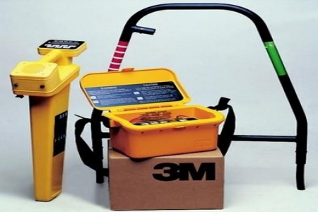
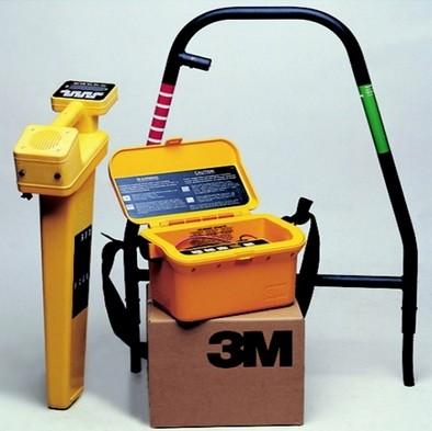
The Cable Fault Detector is a comprehensive cable fault detection instrument. It can test for high-resistance flashover faults, high/low resistance grounding, short circuits, cable breaks, poor contact, and other cable faults.
Technical Specifications
1. Max Test Distance: 32km
2. Detection Blind Zone: 1m
3. Reading Resolution: 1m
4. Power Consumption: 5VA
5. Operating Conditions: ambient temp 0C~+40C (extreme temp -10C~+50C)
Relative Humidity: 40C (20~90)%RH
Atmospheric Pressure: (86~106)kPa
6. Dimensions: 225x165x125mm, Weight: 2kg
1. Traditional Cable Fault Detection Methods
1.1 Resistance Bridge Method
This method has remained largely unchanged for decades. Convenient for short-circuit and low-resistance faults. The bridge method uses the principle that when balanced, the product of corresponding arm resistances is equal, with cable length proportional to resistance.
1.2 Low-Voltage Pulse Reflection Method
Also known as Time Domain Reflectometry (TDR), uses a pulse reflectometer to independently measure low-resistance and open-circuit faults without a high-voltage impulse generator.
1.3 Pulse Voltage Sampling Method
Also known as impulse high-voltage flashover method, used for high-resistance leakage and flashover faults. The cable fault is first broken down under DC or pulsed high voltage, then distance is measured by recording the discharge pulse round-trip time. Includes DC high-voltage flashover and impulse high-voltage flashover methods.
1.4 Traditional Cable Fault Pinpointing Methods
① Acoustic Detection Method
This method uses the breakdown discharge sound at the fault point under high-voltage impulse for precise location.
② Acoustic-Magnetic Synchronization
Traditional Methods
1.1 Resistance Bridge Method
1.2 Low-Voltage Pulse Reflection Method
1.3 Pulse Voltage Sampling Method
1.4 Traditional Cable Fault Pinpointing Methods
① Acoustic Detection Method
This method uses the breakdown discharge sound at the fault point under high-voltage impulse for precise location.
② Acoustic-Magnetic Synchronization
③ Audio Frequency Induction Method
When impulse DC high voltage is applied causing discharge at the fault point, a pulsed magnetic field is generated around the cable. Receiving this signal during acoustic pinpointing confirms the discharge sound originates from the fault point.
③ Audio Frequency Induction Method
Generally used for low-resistance faults. A 1kHz audio signal generator injects current into the cable, emitting electromagnetic waves. The signal is received on the ground, amplified, and sent to headphones or an indicator. The fault point is located based on sound intensity or indicator readings.
Note: The above information and technical parameters are compiled and published by Yangzhou Darui Electric Co., Ltd.