
☎
Service Hotline18952707000
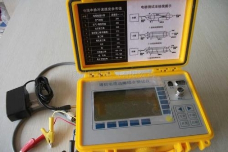
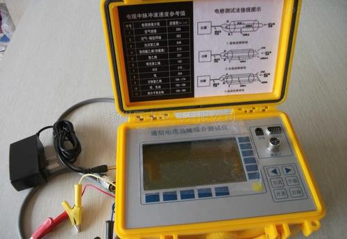
Cable fault locator is a comprehensive cable fault detection instrument that can test high-resistance flashover faults, high and low resistance grounding, short circuits, cable breaks, poor contact, and other faults. The cable fault locator is equipped with an acoustic pinpointing device, which can be used to accurately determine the precise location of the fault point. It is especially suitable for testing various types and voltage levels of power cables and communication cables.
Detection Methods
The cable fault locator adopts multiple detection methods and applies the most advanced electronic technology achievements. It uses computer technology and microelectronics technology, featuring high intelligence, complete functions, wide application range, accurate testing, and convenient operation. Locator Design
Detecting aircraft cable faults is very important in civil aviation maintenance; based on the characteristics of aircraft cables, a method for effective testing and diagnosis—low-voltage pulse method—is proposed. Using single-chip microcomputer and CPLD technology, an aircraft cable defect detection and positioning device is designed; the locator mainly consists of three parts: signal acquisition circuit, system control circuit, and human-machine interaction circuit; at the same time, two sets of crystal oscillators are used to ensure high-speed signal acquisition and meet the low-speed processing of the system, featuring low cost, portability, and accurate testing; in addition to aircraft cable maintenance, it can also be applied to short-distance cable defect detection in telecommunications, electric power, and other sectors.
(Secondary Pulse Method) Working principle in cable fault location: First, a high-voltage pulse of a certain voltage level and energy is applied to the fault cable at the test end to cause the high-resistance fault point to break down and arc. At the same time, a low-voltage pulse for measurement is injected at the test end. When the measurement pulse reaches the high-resistance fault point of the cable, it encounters the arc and reflects on the arc surface. Since the high-resistance fault becomes an instantaneous short-circuit fault during arcing, the low-voltage measurement pulse will exhibit obvious impedance characteristic changes, turning the flashover measurement waveform into a low-voltage pulse short-circuit waveform, making waveform discrimination particularly simple and clear. This is what we call the "secondary pulse method." The received low-voltage pulse reflection waveform is equivalent to a waveform of a core completely short-circuited to ground. By superimposing the low-voltage pulse waveforms obtained when the high-voltage pulse is released and when it is not released, the two waveforms will have a divergence point, which is the reflection waveform point of the fault point. This method combines the low-voltage pulse method with high-voltage flashover technology, making it easier for testers to determine the location of the fault point. Compared with traditional testing methods, the advanced feature of the secondary pulse method is that it simplifies the complex waveform of the impulse high-voltage flashover method into the simplest low-voltage pulse short-circuit fault waveform, making interpretation extremely simple and allowing accurate determination of the fault distance.
Using a double impulse method to extend the arcing time and stabilize the arc, it can easily locate high-resistance faults and flashover faults. The three-pulse method is advanced in technology, simple to operate, clear in waveform, and fast and accurate in positioning. It has become the mainstream positioning method for high-resistance faults and flashover faults. The three-pulse method is an upgrade of the secondary pulse method. Its method is: first, measure the reflection waveform of the low-voltage pulse without breaking down the fault point of the cable under test; then, use a high-voltage pulse to break down the fault point of the cable to generate an arc; when the arc voltage drops to a certain value, trigger a medium-voltage pulse to stabilize and extend the arc time; then send a low-voltage pulse to obtain the reflection waveform of the fault point. After superimposing the two waveforms, it can also be found that the divergence point is the location corresponding to the fault point. Because the medium-voltage pulse is used to stabilize and extend the arc time, it is easier to obtain the fault point waveform than the secondary pulse method. Compared with the secondary pulse method, the three-pulse method does not require selecting the synchronization duration of arcing, making operation simpler.
Note: The above information and technical parameters are compiled and released by Yangzhou Darui Electric Co., Ltd.