
☎
Service Hotline18952707000


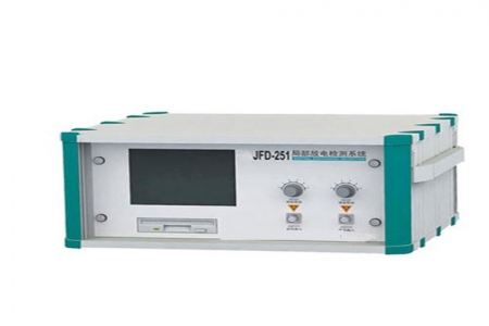
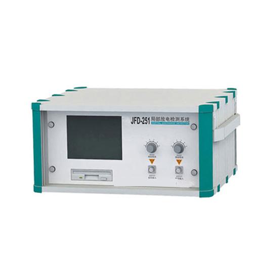
The simulated partial discharge tester is developed by our factory based on the advanced theories in the field of partial discharge measurement at home and abroad, referring to the International Electrotechnical Commission (IEC60270) standard, adopting advanced technology and circuits, and continuously improved after extensive trial use by users in various places. While retaining the advantages and functions of previous generations, it is more complete in design, more convenient in use, and more reliable in performance. The TKJF partial discharge detector features high detection sensitivity, wide applicability to test samples, and high signal-to-noise ratio. It uses a large-screen oscilloscope tube with clear display of test waveforms, high-frequency elliptical scanning (power consumption less than 1 VA), large dynamic range of the amplification system, multiple frequency band combinations (nine types), auxiliary zero marking system, linear and logarithmic dual-function pointer and digital meters, which can simultaneously display the discharge quantity of discharge pulses. The TKJF partial discharge detector is a powerful auxiliary tool for researching and developing new high-voltage electrical products and improving product quality, as well as an effective test instrument for on-site judgment of equipment condition. When used with the JZF-9 or JZF-10 calibration pulse generator, it is especially suitable for power departments, manufacturers, and research institutions.
Working Principle
When partial discharge occurs in the test sample CX under the test voltage, pulse current is generated through the coupling capacitor Ck, and the pulse signal is picked up by the input unit. After amplification by a low-noise preamplifier, selection of the required frequency band by a filter amplifier, and amplification by a main amplifier (to the required amplitude), visible discharge pulses appear on the elliptical scanning baseline of the oscilloscope screen, and the peak value is also sent to the pulse peak meter for display. The time window unit selects a working period within each cycle of the test voltage for the pulse peak meter; during this working period, the corresponding display area on the oscilloscope screen is brightened, which can avoid interference from fixed phases. This is the conventional method for measuring discharge quantity.
When a known charge is injected into the test sample CX using the JZF calibration pulse generator, adjusting the fine adjustment knob of the amplifier so that the value displayed on the discharge meter matches the injected charge allows direct reading of the measured discharge quantity on the meter during voltage application, without the need for calculation, which is very convenient.
The test voltmeter generates a test voltage zero-crossing marking signal through the voltmeter resistor R, which can display a zero marking pulse on the oscilloscope screen. The magnitude of the test voltage can be displayed by the kV meter.
Note: The above information and technical parameters are compiled and released by Yangzhou Darui Electric Co., Ltd.