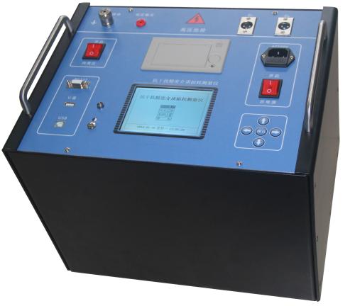

The Loop Resistance Tester (also called Contact Resistance Tester or Micro-ohmmeter) is used in power systems for
The Loop Resistance Tester (also called Contact Resistance Tester or Micro-ohmmeter) is a specialized precision instrument used in power systems for measuring the conductive loop resistance of electrical equipment such as high-voltage switches, circuit breakers, and busbar connection points.
As of 2026, technology in this field has deeply evolved from traditional single measurements toward intelligence, high precision, and big data interaction. The following is a detailed analysis based on the latest industry standards:
1. Core Functions and Importance
Diagnosing "Joint" Health: The contacts of electrical equipment (such as circuit breaker contacts) are like joints in the human body. If contact resistance is too high, abnormal high temperatures will be generated when large currents pass through, leading to contact erosion, welding, or even explosions or fires.
Preventive Maintenance: It is the core tool for implementing the "Regulations for Hand-Over and Preventive Testing of Electric Power Equipment" (such as DL/T 596), used to detect poor contact hazards in advance before equipment commissioning or during periodic maintenance.
Applicable Scenarios: Widely used in power plants, substations, railway power supply systems, and large industrial distribution rooms for testing SF6 circuit breakers, vacuum circuit breakers, and disconnecting switches.
2. Working Principle: DC Voltage Drop Method (Four-Wire System)
Modern Loop Resistance Testers commonly use the four-wire measurement method (Kelvin bridge principle) to eliminate the influence of test lead resistance and contact resistance:
High Current Injection: The internal high-frequency switching power supply outputs a constant high DC current (typically 100A, 200A; some high-end models can reach 400A-600A). High current can effectively break through the oxide film on contact surfaces to measure real contact resistance.
Independent Voltage Sampling: Inside the current loop, the voltage drop at the test point is collected through independent voltage leads.
Ohm's Law Calculation: The built-in high-speed microprocessor calculates based on
R=U/I automatically calculates the resistance value, with resolution typically up to 0.1μΩ.
3. 2026 New Technology Trends and Features
Based on 2026 market evaluations and technical white papers, mainstream equipment features the following characteristics:
Intelligent Operation:
Touch Interaction: Replacing traditional buttons, equipped with 7-inch or larger high-definition color touchscreens, supporting graphical data display and wizard-style operation.
Automatic Conversion: Automatically converts measurement results to standard temperature (such as 20℃ or 75℃), eliminating manual table lookup calculations.
Anti-Interference and Precision Improvement:
Using 24-bit high-precision AD converters and digital filtering technology, maintaining ±0.5% or higher accuracy even in strong electromagnetic interference environments (such as near live busbars).
Features dual-channel synchronous testing, capable of simultaneously measuring data on both sides of break points or multiple phases, doubling efficiency.
Data Ecosystem Connectivity:
Wireless Transmission: Standard Wi-Fi/Bluetooth, test data can be directly uploaded to mobile APP or cloud O&M platform, generating electronic reports.
Large Capacity Storage: Built-in storage can hold thousands of data sets, supporting one-click USB export.
Portability and Battery Life:
Adopting lightweight high-frequency switching power supply technology, overall weight is generally controlled within 10kg, with some models supporting lithium battery power for field operations without external power.
4. Key Selection Indicators
If you need to purchase or use this equipment in 2026, please pay attention to the following parameters:
Table
Parameter Recommended Standard Description
Test Current ≥100A (200A recommended) Higher current provides stronger oxide layer breakdown capability and more realistic data.
Measurement Range 0 ~ 20000 μΩ (20mΩ) Covers measurement from micro-ohm level contacts to milliohm level busbars.
Resolution 0.1 μΩ Capable of capturing minute resistance change trends.
Measurement Accuracy ±(0.5% + 2 digits) Ensures data credibility.
Continuous Operating Time ≥5 minutes (full load) Ensures readings under thermally stable conditions.
Protection Functions Back-EMF protection, overheat protection Prevents instrument damage from inductive loads (such as accidental testing of transformer windings).
5. Common Operating Procedure Overview
Wiring: Using dedicated test leads, clamp current leads (C1/C2) and voltage leads (P1/P2) on both sides of the tested contacts (voltage clamps inside current clamps).
Setup: Power on and select test current range (e.g., 100A).
Testing: Press the "Test" button; the instrument automatically ramps up current, samples, and calculates.
Reading and Printing: Read after values stabilize; data can be printed via built-in printer or saved.
Discharge: After testing, the instrument automatically cuts off current and performs discharge; confirm no voltage before disconnecting leads.
6. Representative Manufacturers and Models (2026 Reference)
Mainstream brands in the market include Wuhan Kaidi Zhengda (KDHL series), Shanghai Duanyi (SDY series), Kanggaote (KGT), and international brands such as Megger and OMICRON.
Typical model examples: KDHL-100A, SDY817A, HDHL-100A, etc. These models were all upgraded to intelligent touchscreen versions in 2026 with enhanced data analysis software.