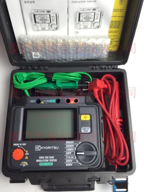
HV Insulation Resistance Tester
Darui Electric recommends:
Product Structure
1. The HV Insulation Resistance Tester consists primarily of three parts.
First: DC high-voltage generator, used to generate DC high voltage.
Second: Measurement circuit.
Third: Display.
(1) DC High-Voltage Generator
Measuring insulation resistance requires applying a high voltage at the measurement terminal. The standard values specified in the national insulation resistance tester standard are 50V, 100V, 250V, 500V, 1000V, 2500V, 5000V, etc.
There are generally three methods for generating DC high voltage. The first is the hand-cranked generator type, accounting for approximately 80% of domestic production (origin of the "megger" name). The second method uses mains transformer step-up and rectification to obtain DC high voltage, commonly used in mains-powered megohmmeters. The third method utilizes transistor oscillation or dedicated PWM circuits to generate DC high voltage, generally adopted by battery-powered and mains-powered insulation resistance testers.
(2) Measurement Circuit
The measurement circuit converts the current signal flowing through the test object into a readable indication, typically using a galvanometer or electronic amplification circuit.
(3) Display
The display shows the measured insulation resistance value, using analog pointer, digital display, or a combination of both.
Note: The above information and technical parameters are provided by Yangzhou Darui Electric Co., Ltd.
 Scan WeChat