TAG-6000 HV Wireless Phase Detector
Darui Electric recommends:
TAG6000 HV Wireless Phase Detector — note that multiple companies have counterfeited TAG5000/TAG6000 models, deceiving consumers.. Counterfeit products use English-labeled panels and are sold to power users at prices matching the original French models, seriously violating consumer rights. Power users are advised not to be misled by low prices, as using counterfeit products may lead to safety incidents.
TAG6000 HV Wireless Phase DetectorInstructions:
I. Overview
The TAG6000 HV Wireless Phase Detector (also known as phase tester, digital phase detector) is used for phase and sequence verification of power lines and substations, with phase detection, sequence testing, and voltage verification functions. It features strong EMC (electromagnetic compatibility) compliance for various interference environments. The high-voltage phase signal is captured by the collector, processed, and transmitted wirelessly. The receiver compares the phase and provides qualitative results. Wireless transmission ensures safe, reliable, fast, and accurate operation for all phasing applications.
II. Safety Precautions
1. During field testing, operators shall follow the requirements of the "Electric Power Safety Work Regulations."
2. The insulated rod provided with this instrument is rated for voltage levels ≤220kV.
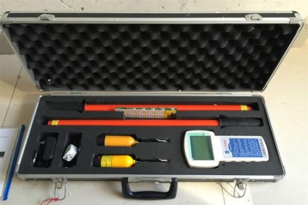
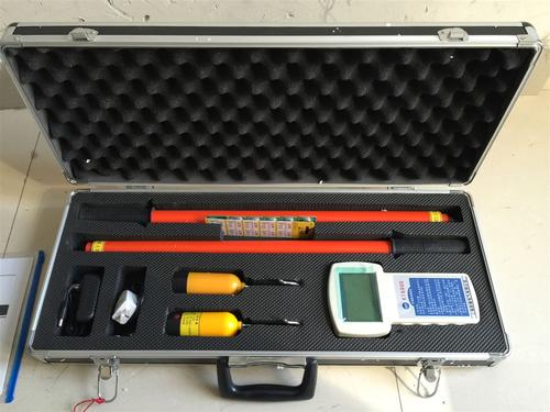
3. TAG6000 Equipment List
① 1× Aluminum Alloy Carrying Case
② 1× Calibration Plug Cable
③ 1× 9V Battery
④ 10× 1.5V Batteries
⑤ 1× User Manual
4. TAG6000 Technical Features
1. Display Content: Wireless HV Phase Detector, Out-of-phase, In-phase, X, Y.
2. Power Supply: Main unit uses 1× battery (NEDA/604/6F22) or equivalent. X and Y collectors each use 5× AG13 batteries.
3. Auto Power-Off: Main unit auto powers off ~15min after startup. 4. Backlight: Press backlight switch when lighting is too dim for reading.
V. Technical Specifications:
① Accuracy: Self-calibration error ≤2°; Field test: In-phase error ≤10°, Out-of-phase error ≤15°
② Sampling Rate: 3 times/sec
③ Main Unit Power: 9V±2V
④ X & Y Collector Power Voltage: 7.5V±1.5V
⑤ Main Unit Operating Current: ≤7mA
⑥ X & Y Collector Operating Current: ≤4mA
⑦ Line-of-Sight Transmission Range — Host to X Collector: ≤80m, Host to Y Collector: ≤50m
⑧ Operating Environment: -35°~+50°C, Humidity: ≤95%RH
⑨ Storage Environment: -40°~+55°C, Humidity: ≤95%RH
⑩ Measurable AC Voltage Range: 0.38kV~500kV
VI. Usage Instructions
1. Main Unit Check
(1) System Self-Calibration
Insert the supplied calibration cable plug into an AC 220V power source, and clamp the two signal test clips to the X and Y collector heads respectively. The main unit display should show X and Y as in-phase, with a phase difference of 000°~001° (if X or Y does not display, reverse the 220V plug).
(2) Field Verification
For field phasing, first place both rods on the same phase to self-calibrate.
2. Usage Method
① Phase determination (in-phase or out-of-phase) is based on the Chinese character display.
During phasing, observe the following host displays:
② X and Y indicate signals received from X and Y rods respectively.
③ If a symbol appears below X or Y, it indicates low battery in the X or Y rod.
④ If a symbol appears above X and Y, it indicates low main unit battery.
⑤ "Wireless HV Phase Detector" appears in top right of display when main unit is powered on.
(3) When X rod, Y rod or main unit battery is low, the system should still operate normally for a period. If the display becomes unstable, replace batteries immediately. Note: X and Y rod batteries must be replaced simultaneously.
(4) If the host display behaves abnormally, power off and restart — the host will auto-recover.
(5) Press the backlight switch to illuminate the display.
3. Collector Check:
Collector Diagram:
(1) To replace batteries: rotate counterclockwise to remove the collector shell, then open the battery cover and replace batteries (AG13 type, 5 pcs).
(2) The collector has two interchangeable contact heads. Rotate counterclockwise to remove and swap.
4. Field Phasing Instructions:
① First, hang X and Y collectors on the same HV line — the display should show X and Y in-phase with phase difference 000°~001°.
② For HV line phasing, arrange X and Y collectors as follows: AA' in-phase 000°~001°; AB' out-of-phase 120° or 240°; BB' in-phase 000°~001°; BC' out-of-phase 120° or 240°; CC' in-phase 000°~001°.
③ For precise values, keep one collector fixed at its measurement point and move the other around the second point in all directions, or swap X and Y, to find the most accurate phase angle.
④ If all AA', AB', BB', BC', CC' readings show out-of-phase, this may be due to different winding configurations of the two supply lines, resulting in 30° or 60° phase difference. Measurement standard for this scenario (30° example): Same test method as ① and ②. Results should be: AA' out-of-phase 30°; AB' out-of-phase 120° or 240°; BB' out-of-phase 30°; BC' out-of-phase 120° or 240°; CC' out-of-phase 30° (Note: 120° and 240° indicate positive or negative phase sequence only).
⑤ For measurements ≥10kV, X and Y may be placed directly on the conductor or insulation sheath for phasing.
⑥ For phasing ≥66kV, X and Y collectors may use contact or non-contact methods. (For 110kV/220kV: place collectors 300mm~1000mm below the HV line. For 500kV: place collectors 1000mm~2000mm below, lateral tolerance ±300mm).
⑦ Phase Sequence Measurement: Assuming a line is Phase A, place X on A and Y on another phase. Displaying 120° indicates positive sequence (this phase is "B"); displaying 240° indicates negative sequence (this phase is "C").
⑧ Voltage Detection: Hang one collector on the HV line. If the corresponding symbol appears on the host screen, the line is live. If not, the line is dead (note: the collector cannot substitute for a dedicated voltage detector).
VII. Maintenance
1. This product is a precision instrument — do not open it casually.
2. Replace batteries at least once per year.
3. Do not store the instrument in humid, high-temperature, or dusty environments.
4. Perform a withstand voltage test on the insulated rod before first use.
5. Perform a withstand voltage test on the insulated rod annually.
Note: The top section of the first insulated rod segment contains a 350mm built-in antenna and must NOT undergo withstand voltage testing. The external insulation between the antenna and rod wall is rated at 15kV.
4. Long-Distance Phasing — Convenient & Fast
Note: The above information and technical parameters are compiled and published by Yangzhou Darui Electric Co., Ltd.