
☎
Service Hotline18952707000
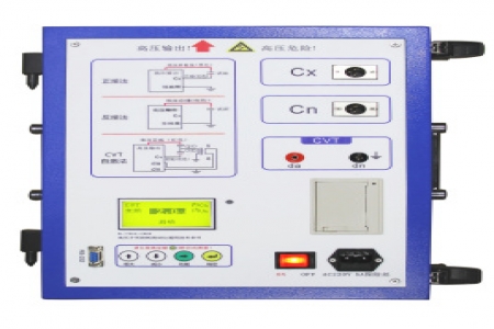
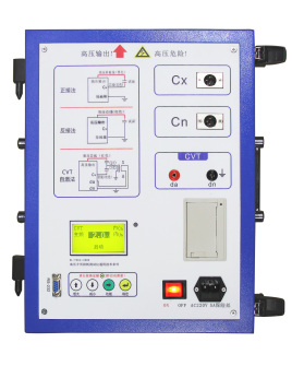
The variable frequency automatic dielectric loss tester is a high-precision testing instrument used in power plants, substations, and other field or laboratory settings to measure the dielectric loss tangent and capacitance of various high-voltage power equipment. The instrument is an integrated structure, built-in dielectric loss test bridge, variable frequency voltage regulating power supply, step-up transformer, and SF6 high-stability standard capacitor. The high-voltage test source is generated by the internal inverter of the instrument and is boosted by the transformer for testing the test object. The frequency can be changed to 45Hz or 55Hz, 55Hz or 65Hz, using digital notch technology to avoid interference from the power frequency electric field, fundamentally solving the problem of accurate measurement under strong electric field interference. It is also suitable for testing with generator power supply after a complete power outage. The instrument can test the dielectric loss of insulating oil when equipped with an insulating oil cup.
Introduction
The variable frequency dielectric loss tester, also known as the variable frequency dielectric loss testing instrument, is a high-precision instrument for fully automatic measurement of the dielectric loss tangent and capacitance of various high-voltage power equipment in power plants, substations, and other field settings. Due to the use of frequency conversion technology, accurate measurement under strong electric field interference is ensured. The instrument uses a Chinese menu operation, and the microcomputer automatically completes the entire measurement process. This instrument is also suitable for measuring tgδ and capacitance of high-voltage electrical equipment in workshops, laboratories, and scientific research units. The instrument can measure ungrounded or directly grounded high-voltage electrical equipment using positive or reverse wiring methods. It can also measure the tgδ and main capacitance C1, C2 of capacitive voltage transformers.
The instrument is equipped with a high-voltage step-up transformer and adopts safety protection measures such as zero-crossing switching and lightning protection. During the test, it outputs high voltage of different levels from 0.5KV to 10kV, making operation simple and safe.
Tester Features
◆ Simple operation, Chinese display, printing
◆ Convenient to use, no conversion required
◆ The variable frequency dielectric loss tester comes with built-in high voltage, strong anti-interference ability, short test time, etc.
Tester Parameters:
1. High voltage output: 0.5 ~ 10kV, each step increases by 500V, total 20 steps
High voltage output cable, can be dragged on the ground
Three frequencies: 45Hz, 50Hz, 55Hz
2. Capacity: 1500VA
3. Accuracy: tgδ: ±(reading*1.0%+0.08%)
Cx: ±(reading*1.5%+5PF)
4. Resolution: tgδ: 0.01% Cx: 1pF
5. Measurement range: 0.1% < tgδ < 50%
3PF < Cx < 60000PF
At 10KV, Cx ≤ 30000PF
At 5KV, Cx ≤ 60000PF
6. Power supply: AC 220V ±10% 50±1Hz
7. Harmonic adaptation: ≤3%
8. Operating conditions: -15℃ to 50℃, relative humidity <80%
9. Dimensions: 460 (L) × 335 (W) × 340 (H)
10. Weight: 30 kg
Working Principle:
After the variable frequency dielectric loss tester starts measurement, the high voltage set value is sent to the variable frequency power supply. The variable frequency power supply uses a PID algorithm to slowly adjust the output to the set value. The measurement circuit sends the actual high voltage to the variable frequency power supply, fine-tuning the low voltage to achieve accurate high voltage output. According to the positive/reverse wiring setting, the measurement circuit automatically selects the input and switches the range based on the test current. The measurement circuit uses Fourier transform to filter out interference, separates the fundamental wave of the signal, performs vector operations on the standard current and the test object current, calculates the capacitance from the amplitude, and calculates tgδ from the phase angle difference. Multiple measurements are repeated, and an intermediate result is selected after sorting. After the measurement is completed, the measurement circuit issues a voltage reduction command, and the variable frequency power supply slowly reduces the voltage to 0.
Note: The above information and technical parameters are compiled and released by Yangzhou Dara Electric Co., Ltd.