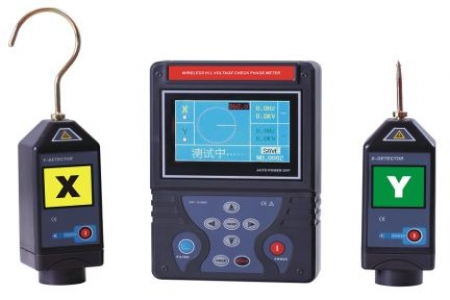
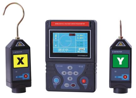
HV Wireless Phase Detector uses the latest power electronics detection technology and wireless transmission technology. Safe, reliable and convenient to operate. Overcomes the limitations of wired phase detectors. Complies with national power safety tool testing standards.
Principle and Structure
The HV Phase Detector consists of two electrically isolated transmitters and receivers, each equipped with electrodes that connect to (or contact) the conductor under test. The red transmitter has a hook-shaped electrode for hanging on the conductor; the yellow receiver has a Y-shaped electrode for convenient contact. These electrodes serve as antennas for transmitting and receiving signals. Both transmitter and receiver ends connect to matching insulating operating rods.
During normal operation, the transmitter processes and modulates the collected grid voltage signals with phase relationships, then transmits them to the receiver. The receiver demodulates the phase-characteristic signals and compares them in real-time with the phase-related voltage signals it collects, measuring the phase difference. The PD-I HV Phase Detector considers phase difference less than 10° as in-phase, and greater than 30° as out-of-phase.
Precautions and Maintenance
1. Antennas must be installed before frequency transmission calibration. The detector housing is made of polycarbonate and must be kept clean. Remove all dirt or moisture. After each use, wipe the instrument with a cloth dampened with silicone oil.
2. Store the instrument properly in its case when not in use.
3. In low temperature environments (-10°C or lower), store the instrument in a warm place. Cold batteries may fail.
4. Test the instrument before each use.
HV Wireless Phase Detector
I. Design Objectives:
The HV Phase Detector is designed to achieve: verification of grid structure, circuit diagram mapping, confirmation of relative phase for different conductors in three-phase connections, with no electrical connection between the two measurement components, making the device highly flexible and safe.
Please Note:
▲ This device uses radio frequency transmission technology. Its basic working principle is real-time phase comparison.
▲ The device can detect the presence of rated voltage.
▲ Measured phase angle within +10° is considered in-phase.
▲ Greater than +30° is considered out-of-phase.
II. Structural Principle:
Includes two electrically isolated components with electrodes for connecting to the conductor under test. One orange transmitter with a hook-shaped electrode for hanging on the conductor, and one yellow receiver with a Y-shaped electrode for convenient contact. These electrodes serve as antennas for transmitting and receiving signals. Both ends connect to insulating operating rods. The transmitter has dual functions operating in sequence.
Step 1: Detect voltage on the conductor under test. Functions as a voltage detector, emitting intermittent audible and visual signals for live conductors.
Step 2: After voltage detection (5-10 seconds), the transmitter automatically switches to phase measurement mode, continuously transmitting a phase-characteristic RF signal to the receiver. In this mode, the line also functions as an antenna. Continuous light indication shows the transmitter is operating in sequence. The receiver serves only one purpose: in-phase measurement while the transmitter operates. To:
1) Ensure voltage is present on the conductor;
2) Receive RF signals from the transmitter;
3) Compare measured phase with received phase-characteristic signals in real-time;
4) When in-phase, the receiver outputs a continuous strong light and sound signal; when out-of-phase, the receiver outputs a weak light signal, indicating only that the contacted conductor has voltage.
The transmitter and receiver include an integrated test system for testing all components: electrical elements, batteries, circuits, and antennas. This test is equivalent to actual line contact testing. The transmitter and receiver have no switch buttons; they automatically start working upon contact with a live line, and immediately stop when the measurement electrode loses contact with the conductor.
III. Calibration:
1. Single Transmitter — Orange:
The transmitter module has a signal generator operating at a frequency close to grid frequency. Pressing TestButton immediately starts signal generation. The internally generated signal passes through the electrode to the antenna, simulating actual line contact.
◆ Attach hook-shaped electrode
◆ Press and hold TestButton
◆ All 4 LEDs flash once per second, buzzer sounds synchronously.
◆ After a few seconds, sound and flashing stop. Only LED1 remains lit as long as TestButton is held.
◆ If the above indications are not observed (some LEDs not lit or no sound), replace the battery.
2. Single Receiver — Yellow:
The receiver module is identical to the transmitter. Pressing TestButton immediately starts operation. The internally generated signal passes through the electrode to the antenna, simulating actual line contact.
◆ Attach Y-shaped electrode
◆ Press and hold TestButton
◆ LED1 stays lit without flashing. When holding TestButton, buzzer emits only a very short single sound. LED2, LED3, LED4 flash once simultaneously. If the above indications are not observed, replace the battery.
IV. RF Transmission Calibration:
The internal module generates frequencies close to grid frequency. With electrodes (antennas) installed, calibration can be performed in two ways.
1. Full Self-Calibration:
◆ Hold one unit in each hand
◆ Press transmitter TestButton until it enters phase measurement mode
◆ Press both transmitter and receiver TestButtons simultaneously. If RF transmission is correct, receiver LED2/3/4 flash rhythmically, buzzer sounds synchronously, LED1 stays lit.
◆ This test can be performed by 2 people: one holds the transmitter vertically (electrode up), the other holds the receiver the same way. Distance: at least 3m (up to ~10m). Shorter than actual use because air transmission is weaker than line transmission.
2. Both Units on Live Grid Test:
◆ Connect both units to the same phase on a live grid; both units’ LED indicators will illuminate synchronously with sound.
◆ Press receiver TestButton
◆ Subsequent behavior is the same as Section 1 above.
◆ Transmission distance ~7m, slightly longer than Section 1 because signals travel along power lines. Still less than actual measurement distance since the receiver only has its own electrode as antenna.
3. Two-Unit Live Grid Verification:
◆ Connect both units to different phases on a live grid; LED indicators will show different phase indication.
◆ Press either TestButton for details. The receiver displays out-of-phase indication.
V. Main Functions and Technical Parameters:
|
Applicable Voltage
|
6KV-220KV
|
|
Insulating Rod Length
|
1m x 4 pcs (110KV + 3 insulating rods)
|
|
Wireless Range
|
0-100m (customizable)
|
|
Operating Frequency
|
50Hz
|
|
Power Supply
|
9V Battery
|
|
Ambient Temperature
|
-20°C to +50°C
|
|
Manufacturer
|
Shanghai Yiren Electric Co., Ltd.
|
VI. Measurement Operation:
Before and after using the instrument, perform a full auto-test on the complete set (with electrodes attached). Line voltage measurement (using transmitter only)
◆ Screw the hook electrode onto the top of the transmitter. For 110KV measurement, add a short rod to the top of the transmitter operating rod.
◆ Attach the operating rod to the transmitter with electrode installed.
◆ Hang the transmitter hook onto the line under test. The operator can see on the back of the transmitter: 4 LED indicators: LED1-LED4; one TestButton; one buzzer;
Note: The above information and technical parameters are compiled and published by Yangzhou Darui Electric Co., Ltd.