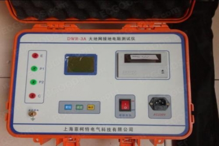
Contact Loop Resistance Tester
Darui Electric recommends:
GHHL Contact Loop Resistance Tester, also known as Loop Resistance Tester or High-Current Micro-ohmmeterIt is a specialized tester for contact resistance of high/low voltage switches, cables, wires, and welded joints. Its current adopts the standard current recommended by national standard GB736, enabling resistance measurement under standard current conditions. The instrument features compact size, light weight, strong anti-interference capability, high precision, easy operation, and comprehensive protection. It meets the requirements of power supply departments for on-site HV switch maintenance and factory loop resistance testing.
Types and Applications
Earth resistance meter: suitable for direct measurement of grounding resistance of various devices, also for general low resistance measurement. The 4-terminal (0~1~10~100Ω specification) model can also measure soil resistivity.
Single-Clamp Loop Resistance Tester
Unique single-clamp design avoids dual-clamp probe interference. No auxiliary ground stake needed — clamp and measure directly.
Universal Ground/Insulation Resistance Tester
Multiple test methods: dual-clamp ground resistance, 4-pole ground resistance, soil resistivity, insulation resistance, AC/DC resistance, current RMS testing.
Ground Impedance Tester
Clamp-type earth resistance meter: no auxiliary ground rods needed, no need to disconnect the equipment ground. Simply clamp onto the ground wire or rod to measure ground resistance down to 0.1Ω. Can also measure current.
Loop Resistance Tester
Microprocessor controlled for high accuracy and reliability. Three LED indicators for wiring status. Direct reading of short-circuit protection current and ground fault current. Auto-lock on overheating.
Digital Ground Resistance Tester
Specialized for measuring ground resistance of electrical equipment, lightning rods, etc. All-electronic instrument with key circuits using Texas Instruments ICs. Advanced testing principle.
Double-Clamp Ground Resistance Tester
Multiple ground resistance measurement methods: no auxiliary electrode / 3-pole / 4-pole / 2-pole — suitable for various measurement environments. Wide measurement range: 0.002Ω–300KΩ — meets diverse requirements.
Ground Resistance Tester
Working Principle
The loop resistance tester uses PWM high-frequency switching power supply to provide >100A test current. When measurement is triggered, the HF switching power supply outputs >100A test current while the sampling circuit begins sampling. The signal is amplified, converted from analog to digital by A/D converter, then filtered, computed, and processed by the microprocessor, finally displaying current and resistance values. After 10 seconds, the system auto-resets. When measured loop resistance is <400μΩ, minimum resolution is 0.1μΩ; when >400μΩ, minimum resolution is 1μΩ.
Switch Loop Resistance Tester — Test Principle:
1. 50Hz AC rectified to 15KHz HF power, then transformed to LV DC. Feedback from voltage drop across load. PWM technology achieves automatic constant current.
2. 100A DC test current through DUT produces voltage drop. Internal reference resistor provides comparison. Higher accuracy than conventional bridge testing.
Note: The above information and technical parameters are compiled and published by Yangzhou Darui Electric Co., Ltd.